
The WS2812B from the WS2812 series has been my favorite RGB chip when it comes to projects where lighting in different colors is involved. Not so long ago, I got notice that there is a successor on the market for already some time. The new RGB chip is called WS2813, which also comes in different variants (e.g. WS2813A, WS2813B, WS2813C,…). In this post, I want to give an introduction into the new features of the new RGB chip and give a short tutorial about WS2813-based RGB rings.
WS2813 Introduction
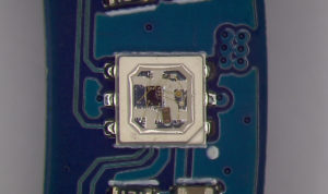
According to the official data sheet of Worldsemi, the first version of the WS2813 was introduced in 2017. At the first look, the WS2813 has the same functionalities as its predecessors: It’s a small chip with an integrated multi-color LED that can light up in different colors (three primary colors with 256 brightness level → corresponds to 256*256*256= 16777216 colors). Moreover, the RGB chip can be controlled with a single control wire – in addition to the GND- and 5V power signal. The control wire can also be used for cascading multiple RGB chips in order to form an “LED strip” or an “LED ring”.
What are the WS2813’s main features compared to the previous versions (e.g. 2812B)?
- Dual-signal wires: The control wire is basically doubled by introducing an additional input “backup control data signal input” next to the “control data signal input”. As a result, if a single RGB chip of an LED strip get damaged, the damage does not affect the RGB chips to follow.
- Increase of refresh frequency: Compared to the WS2812 series, the refresh frequency has been increased from 400 Hz to 2000 Hz.
Fortunately, existing libraries, such as FastLED, Adafruit_NeoPixel, can be used to control also WS2813 RGB chips. Next, I give a tutorial that shows how to control RGB rings.
Tutorial: Controlling WS2813B-Mini RGB Rings with an Arduino Uno
My guess is that most people probably make use of RGB chips in form of LED strips. Alternatively, there are also LED/RGB rings on the market. Recently, I got hand on two variants of Seeedstudio’s RGB LED Ring series which come with WS2813B-Mini RGB chips. In this tutorial, I want to show how to control such an RGB LED Ring with an Arduino Uno.
List of materials:
Wiring Pin Layout:
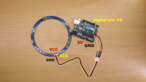
The wiring is very simple as only three wires have to be used to connect the Arduino with the LED Ring. I used the “Grove connector” of the LED Ring to make my connections. Grove is a feature available for many components from Seeedstudio. It makes it easier for beginners to connect components, e.g., to an Arduino. Basically, grove users get a shield for their Arduino and then can use standardized connectors to make connections between the components and the shield. Luckily, conventional jumper wires fit very well into the Grove connectors.
Regarding the actual wiring, Arduino’s 5V pin has to be connected to the VCC pin of the LED ring, Arduino’s GND to GND, and Arduino’s digital pin #6 to SIG.
Programming:
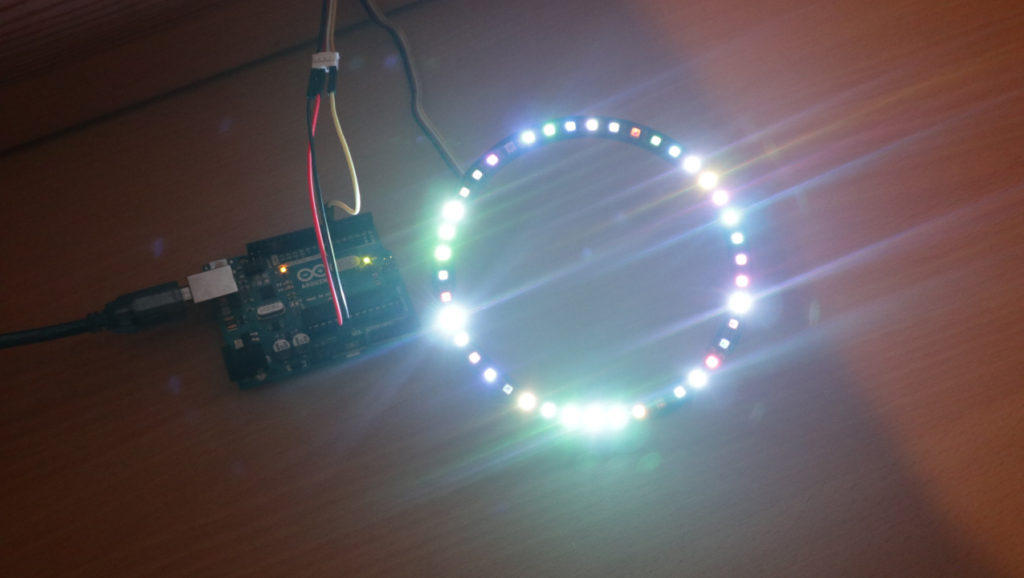
The program represents a very basic lightning demo for the LED ring. The program “walks over” each RGB chip and sets it to a random color. If it has “walked over” all RGB chips, it starts again and overwrites the existing colors with a new random color.
The program is based on the FastLED library which has to be installed on your Arduino IDE installation (Tools -> Manage Libraries…). After including the header file of the FastLED library, the number of available LEDs has to be configured. The actual number depends on your LED ring type. I added a comment to the code about numbers from LED ring types that I’m aware of. In the setup function, FastLED is initialized. Here, you can simply configure it with type WS2813 since the new RGB chip has already been considered by the developers of FastLED.
In each loop function call, an index is incremented. This index represents the “current” RGB chip that is set with a random color. If the index is greater than the number of available RGB chips on the LED ring, it is set back to zero and the whole procedure starts again.
// (c) Michael Schoeffler 2019, http://www.mschoeffler.de

/*
 * This program demonstrates how to use RGB LED Rings. The program "walks over" each LED and sets it to a random color.
 * If you are already familiar with programming LED stripes, you will recognize that there is basically no difference.
 * The code has been written for the Ultimate RGB LED Ring v1.0, but can easily be adapted.
 *
 */

#include "FastLED.h"

// some LED numbers that I'm aware of...
// Grove - RGB LED Ring (16-WS2813 Mini): 16 LEDs
// Grove - RGB LED Ring (20-WS2813 Mini): 20 LEDs
// Grove - RGB LED Ring (24-WS2813 Mini): 24 LEDs
// Grove - Ultimate RGB LED Ring: 42 LEDs

#define NUM_LEDS 42 // add number of LEDs of your RGB LED Ring here
#define PIN_LED_RING 6 // digital output PIN that is connected to DIN of the RGB LED Ring
#define UPDATE_TIME 250 // each 250ms, a new random color is set

CRGB rgb_led_ring[NUM_LEDS]; // color array of the LED RGB Ring

unsigned index = 0; // index represents the currently "walked over" LED

void setup() {
  FastLED.addLeds<WS2813, PIN_LED_RING>(rgb_led_ring, NUM_LEDS); // Change WS2813 to something else, if your RGB LED Ring has a different chipset (e.g. WS2812B instead of WS2813).
}

void loop() {
  rgb_led_ring[index] = CHSV(random8(),random8(),random8()); // we set the color of the LED represented by index
  index++; // index is increased, i.e. the color of the LED to the right is set next time.

  FastLED.show(); // state of color array is transfered to RGB LED Ring

  if (index >= NUM_LEDS) { // if we "walked over" all LEDs, we start from the beginning again.
   index = 0;
  }

  delay(UPDATE_TIME); // program waits for 250ms
}
Programming variant: Two RGB LED Rings
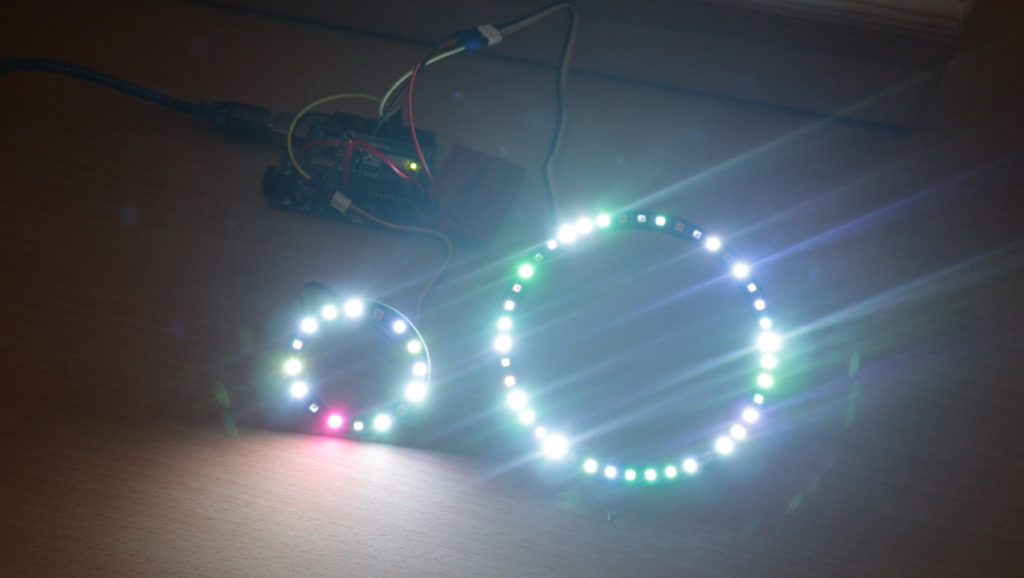
Some time ago, I made a tutorial about WS2812B-based LED strips. Multiple times, I was asked how to apply the program when having two LED strips. If you make use of FastLED, you can just register a second LED strip (or LED ring) to FastLED in the setup function. I changed the previous program in order to be able to control two LED rings. (Ultimate RGB LED Ring with 42 LEDs and RGB LED Ring “16-WS2813 Mini” with 16 LEDs) . Basically, I just copy’n’pasted each line and made slight changes. Regarding the wiring, I connected the GND of the second ring to a GND pin of the Arduino and then I used a mini breadboard to split up the 5V pin of the Arduino in order to draw 5V connections to both rings. As a last step, I connected the SIG pin to Arduino’s digital pin #7.
// (c) Michael Schoeffler 2019, http://www.mschoeffler.de

/*
 * This program demonstrates how to use two RGB LED Rings at the same time. For each RGB LED Ring, the program "walks over" each LED and sets it to a random color.
 * If you are already familiar with programming LED stripes, you will recognize that there is basically no difference.
 * The code has been written for the Ultimate RGB LED Ring v1.0, but can easily be adapted.
 *
 */

#include "FastLED.h"

// some LED numbers that I'm aware of...
// Grove - RGB LED Ring (16-WS2813 Mini): 16 LEDs
// Grove - RGB LED Ring (20-WS2813 Mini): 20 LEDs
// Grove - RGB LED Ring (24-WS2813 Mini): 24 LEDs
// Grove - Ultimate RGB LED Ring: 42 LEDs

#define NUM_LEDS_RING1 42 // add number of LEDs of the first RGB LED Ring here
#define NUM_LEDS_RING2 16 // add number of LEDs of the second LED Ring here

#define PIN_LED_RING1 6 // digital output PIN that is connected to DIN of the first RGB LED Ring
#define PIN_LED_RING2 7 // digital output PIN that is connected to DIN of the second RGB LED Ring

#define UPDATE_TIME 250 // each 250ms, a new random color is set

CRGB rgb_led_ring1[NUM_LEDS_RING1]; // array representing the color layout of the first ring
CRGB rgb_led_ring2[NUM_LEDS_RING2]; // array representing the color layout of the second ring

unsigned index_ring1 = 0; // index represents the currently "walked over" LED of the first ring
unsigned index_ring2 = 0; // index represents the currently "walked over" LED of the second ring

void setup() {
  FastLED.addLeds<WS2813, PIN_LED_RING1>(rgb_led_ring1, NUM_LEDS_RING1); // Change WS2813 to something else, if the first RGB LED Ring has a different chipset (e.g. WS2812B instead of WS2813).
  FastLED.addLeds<WS2813, PIN_LED_RING2>(rgb_led_ring2, NUM_LEDS_RING2); // Change WS2813 to something else, if the second RGB LED Ring has a different chipset (e.g. WS2812B instead of WS2813).
}

void loop() {
  rgb_led_ring1[index_ring1] = CHSV(random8(),random8(),random8()); // we set the color of the LED represented by index (first ring)
  index_ring1++; // index is increased, i.e. the color of the LED to the right is set next time.

  rgb_led_ring2[index_ring2] = CHSV(random8(),random8(),random8()); // we set the color of the LED represented by index (second ring)
  index_ring2++; // index is increased, i.e. the color of the LED to the right is set next time.

  FastLED.show();

  if (index_ring1 >= NUM_LEDS_RING1) { // if we "walked over" all LEDs, we start from the beginning again (first ring)
   index_ring1 = 0;
  }
  if (index_ring2 >= NUM_LEDS_RING2) { // if we "walked over" all LEDs, we start from the beginning again (second ring)
   index_ring2 = 0;
  }

  delay(UPDATE_TIME); // program waits for 250ms
}
Video tutorial

[…] I already made a tutorial on how to use WS2812B-based LED strips. With the knowledge you gain by this tutorial, it should be easily possible to control also other LED chips or LED components, such as LED rings. If you plan to use LED rings, have a look at my WS2813 LED ring tutorial. […]
Great!!
But, my Order 8×8 WS2812b was with 8×8 WS2813 anwers.
I can only use a matrix, the second will not work.
One of the 8×8 WS2813 /QYF-2813-64) work fine with all sketches and library.
Also in parallel operation D4 to Din of the first 8×8 WS2813 and D6 to Din of the 8×8 WS2813 both work well together even in parallel operation
So i connect the second after the first ( First Dout to Second Din ;-(((,
I can do, what i will (can), but but the second remains dark.
What am i doing wrong???
Do you perhaps have an answer???
Best regards
Preuß