
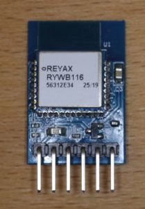
Reyax’s RYWB116_Lite is a breakout board featuring the RYWB116 module. The RYWB116 module is based on Redpine Signals’ RS9116 technology and features a multi-protocol wireless stack including WLAN 802.11 b/g/n and Bluetooth 5. The breakout board simplifies to harness the RYWB116’s capabilities due to ready-to-use connection pins for serial communication. This beginners guide gives a brief introduction into the capabilities of the RYWB116. Moreover, it shows how to setup a WLAN Access Point by sending commands via a serial communication. Finally, a TCP server is created that could be used as HTTP web server.
Official Website: http://reyax.com/products/rywb116_lite/ (Specs, datahseet, etc.)
Equipment:
RYWB116_Lite/RYWB116 Capabilities + Pin layout
The RYWB116 module support multiple WLAN (IEEE 802.11b, 802.11g, 802.11n) and Bluetooth (5, 2.1+ EDR, LE, LE 2 Mbps) standards. The module can run in different modes, e.g.:
- Wi-Fi Access Point (with support for up to 8 clients)
- Wi-Fi Client
- Wi-Fi Direct
- Bluetooth Classic (EDR v 2.1)
- Wi-Fi Client + Bluetooth Low Energy
Later in this guide, we will utilize the “Wi-Fi Access Point”-mode and start a TCP server.
The following table shows the most import specification values of the RYWB116_Lite breakout board (not RYWB116, e.g. differences between RYWB116_LITE and RYWB_116 in operating voltage):
| Item Name | Min. Value | Typical Value | Max. Value |
|---|---|---|---|
| Operating Voltage | 2.1V | 3.3V | 3.6V |
| Baud Rate | 9600 | 115200 | 921600 |
| TX Mode Current | 400 mA | ||
| WLAN Data Transfer Average Current | 270 mA | ||
| WLAN Data Receive Average Current | 48.2 mA | ||
| Receive Power | 10 dBm | ||
| WLAN Operating Frequency | 2.412 GHz | 2.484 GHz | |
| WLAN Bandwidth | 20/40 MHz | ||
| Bluetooth Operating Frequency | 2.402 GHz | 2.480 GHz | |
| Bluetooth Data Rates | 125 Kbps | 3000 Kbps | |
| Operating Temperature | -40 °C | +25 °C | +85 °C |
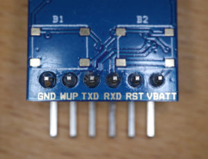
The RYWB116_Lite has six pins which makes it easy to connect the breakout board with a microcontroller, such as the Arudino or STM32. Of course, it is also possible to connect it with an ESP8266 or ESP32. However, as both of them already come with ready-to-use wireless technology, it depends on the use case whether it makes sense or not. When connecting the RYWB116_Lite to a microcontroller, keep in mind that the operating voltage is 3.3V. If a 5V signal is connected to the breakout board, the board might be damaged. The following table gives more details on the pin layout:
| Pin Name | Input/Output | Description |
|---|---|---|
| VBATT | Input | Input supply voltage (2.1-3.6V). |
| RST (RESET_N) | Input | Active-low reset asynchronous reset signal. |
| RXD (UART1_RX) | Input | UART 1 interface serial input. |
| TXD (UART1_TX) | Output | UART 1 interface serial output. |
| WUP (BL_HOST_CMD_BYP/ULP_WAKEUP_IN) | Input | This signal has two functionalities – one during the bootloading process and one after the bootloading. During bootloading, this signal is an active-high input to indicate that the bootloader should bypass any inputs from the Host processor and continue to load the default firmware from Flash. After bootloading, this signal is an active-high input to indicate that the chip/module should wakeup from its Ultra Low Power (ULP) sleep mode. |
| GND | – | Ground |
How to send commands to the RYWB116 module via Serial Connection: Hardware setup
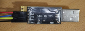
In order to send commands to the RYWB116 module the breakout board has to be connected to a PC. This can be achieved by so-called “USB-to-TTL” devices (come with different names, e.g. USB-to-Serial) that can be plugged in like normal USB devices. Moreover, these “USB-to-TTL” devices have pins that can be connected to the pins of the RYWB116_Lite breakout board. There exist different variants of “USB-to-TTL” devices. The one that I own support 3.3V and 5V operating voltage modes. In order to activate 3.3V mode (and deactivate 5V mode) a jumper has to be set.
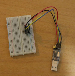
In order to make it work, the USB-to-TTL device and the RYWB116_Lite have to be wired correctly. Besides the correct voltage supply, the RX and TX pins have to wired in order that one’s TX pin (transmit) goes to the other’s RX pin (receive). If you have any doubts, whether your device has the correct voltage level, check with a multi meter. The following table shows how I connected my device to the breakout board:
| USB-to-TTL Pin | RYWB116_Lite Pin |
|---|---|
| 5V | no connection / yellow jumper with USB-TO-TTL VCC |
| VCC | no connection / yellow jumper with USB-TO-TTL 5V |
| 3V3 | VBATT |
| TXD | RXD |
| RXD | TXD |
| GND | GND |
If the USB-to-TTL device is connected to a USB port of the PC, the PC is ready to send signals to the RYWB116 module from the hardware’s point of view. Some USB-to-TTL devices require special drivers: In my case, I had to install a driver called “CH340/CH341 USB to serial port”, before I could work with the device.
How to send commands to the RYWB116 module via Serial Connection: Software setup
Besides the setting up the hardware, a so-called “terminal program” software is required to send the commands to the module. There are many terminal programs available. At time of writing, the one I like most is HTerm from Tobias Hammer. HTerm has all functions that we need to conveniently configure and command the RYWB116 module:
- Supports all available hardware and virtual USB serial rs232 ports
- Supports all baud rates provided by the port + Parity and flow-control
- Input and output in ASCII, hexadecimal, binary and decimal
- Support for predefined command sequences (XML configuration files)
This beginner guide does not cover an introduction into HTerm or terminal programs in general. Therefore, if you have never used a terminal program before and/or are struggling with the following the remaining part of the guide, search the Internet for some basic tutorials on terminal programs. Here are some additional hints:
- With HTerm, you can send data in different formats (ASCII text, HEXADECIMAL, DECIMAL). It can make sense to switch between formats when entering data.
- Moreover, HTerm has many options on how to represent data that has been sent or received (different formats, when to show a new line,…). I strongly recommend to play around with these options in order to find a representation configuration that seems convenient to you.
- If you do not get any response from the device anymore, remove it from the USB port and plug it in again.
How to send commands to the RYWB116 module via Serial Connection: Tutorial
Please keep in mind that the following instructions does not cover any error handling and other additional aspects. The idea is to show the fastest way to create a TCP server.
As a first step, we have to establish a connection to the RYWB116 module via the USB-to-TTL device. HTerm shows you all available ports (Windows: COM1, COM2, COM3,…) that are ready to be connected. If you have some additional serial devices connected to your PC, multiple ports will show up. The easiest solution to identify the port of the USB-to-TTL device might be to just plug it out, have a look which port is missing, and then plug it in again, and then, the missing port should reappear. As shown in the specification values table, the RYWB116 support different baud rate values. The standard parameter to establish a serial connection are: baudrate 115200, data bits per character 8, stop bits 1, parity none, and flow control none.
When starting the serial connection, a sequence of commands has to be send to the RYWB116 module. HTerm support to import predefined sequences files, so that a user can easily send commands that have been defined in the imported sequence file. In the following, you find an HTerm sequence file that contains the commands used in the next part of this guide. To import the sequence file, save the content as XML and import it into your HTerm Sequence Overview.
<HtermSequenceFile>
    <ItemList>
        <SequenceItem name="Baudrate Detection - Start">
            <description></description>
            <sequence value="h[1C]" />
        </SequenceItem>
        <SequenceItem name="Baudrate Detection - End">
            <description></description>
            <sequence value="h[55]" />
        </SequenceItem>
        <SequenceItem name="Firmware - Select Default Firmware (1)">
            <description>Load defualt firmware</description>
            <sequence value="h[31]" />
        </SequenceItem>
        <SequenceItem name="Init - Operation Mode">
            <description>This command sets the operating mode of the module.</description>
            <sequence value="a[at+rsi_opermode=6,1,48,0] h[0D] h[0A]" />
        </SequenceItem>
        <SequenceItem name="Init - Band">
            <description>This command sets the operating band of the module.</description>
            <sequence value="a[at+rsi_band=0] h[0D] h[0A]" />
        </SequenceItem>
        <SequenceItem name="Init - Initialization">
            <description>This command initializes the module.</description>
            <sequence value="a[at+rsi_init] h[0D] h[0A]" />
        </SequenceItem>
        <SequenceItem name="Config - IP Configuration">
            <description>This command can be used optionally in this flow to configure the IP (192.168.50.1 in this example) of the AP. If this command is not issued, a default IP of 192.168.100.76 will be used.</description>
            <sequence value="a[at+rsi_ipconf=0,192.168.50.1,255.255.255.0,192.168.50.1] h[0D] h[0A]" />
        </SequenceItem>
        <SequenceItem name="Config - AP Configuration">
            <description>This command will configure the SSID of the AP to “REYAX” and password will be set to “12345678”.</description>
            <sequence value="a[at+rsi_apconf=1,REYAX,2,2,12345678,300,2,4] h[0D] h[0A]" />
        </SequenceItem>
        <SequenceItem name="Start AP">
            <description>This command will create the Access Point with SSID reyax where xy is a pair of alphanumeric character.
A client device (Named "Device A" in this example) can now associate to the AP, open sockets and transfer data.</description>
            <sequence value="a[at+rsi_join=REYAX,0,2] h[0D] h[0A]" />
        </SequenceItem>
        <SequenceItem name="Start Server">
            <description>Opens a server TCP socket inside the module with port number 5001 with tos (type ofservice) type 0 and max clients support count as 5. A client socket at the remote node (Device A) can connect to the server socket</description>
            <sequence value="a[at+rsi_ltcp=5001,5,0] h[0D] h[0A]" />
        </SequenceItem>
    </ItemList>
</HtermSequenceFile>
Let’s start with sending some commands. As an initial step, an auto baud rate detection (ADBR) procedure takes please. We start this procedure by sending 0x1C to the module. The module responds with 0x55. Then, we sent also 0x55 to the module which completes the procedure.
< 0x1C
> 0x55
< 0x55
Next, the module boots up and shows a welcome message (bootloader menu):
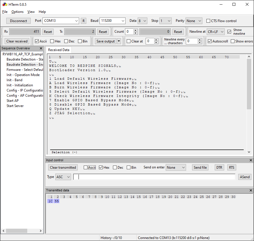
We select options “1” (Load Default Wireless Firmware) by sending “1” as ASCII text (in the following, commands are send in ASCII format denoted with “”).
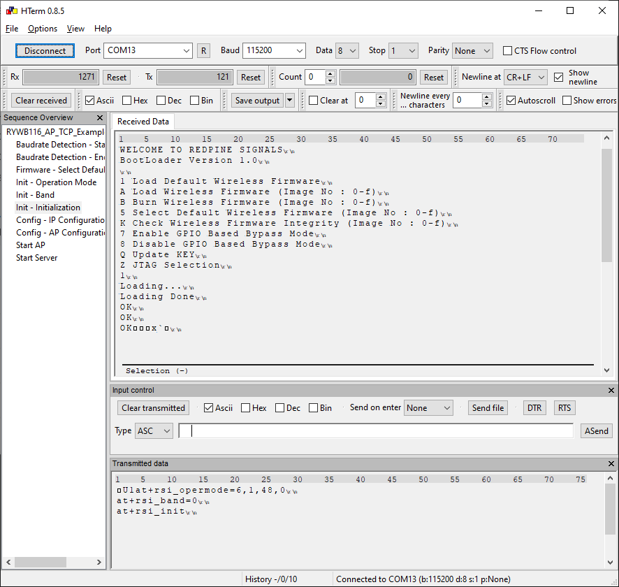
< "1"Now, we can start to configure the Access Point that we want to open up with the RYWB116 module. First, we configure the operation mode to access point mode (first parameter: 6=Access Point Mode, see more details in specification):
< "at+rsi_opermode=6,1,48,0\r\n"
> "OK\r\n"
Next, we set the band (0=2.4Ghz):
< "at+rsi_band=0\r\n"
> "OK\r\n"
Next step is to initialize the module:
< "at+rsi_init\r\n"
> "OK< macAddr >\r\n"
Now, the module is initialized. In addition to an “OK”-confirmation, the module reponds with its MAC address (might result in cryptic characters if received data is shown as ASCII text):
The next step is to configure the IP (192.168.50.1 in this example) of the AP. If this command is not issued, a default IP of 192.168.100.76 will be used. The module will respond with the MAC address, IP address, net mask and gateway IP:
< "at+rsi_ipconf=0,192.168.50.1,255.255.255.0,192.168.50.1\r\n"
> "OK< macAddr >< ipaddr >< netmask >< gateway >\r\n"
Next, the Access Point’s name, password etc. is configured. In this guide, we open an Access Point with the name “REYAX” and password “12345678”.
< "at+rsi_apconf=1,REYAX,2,2,12345678,300,2,4\r\n"
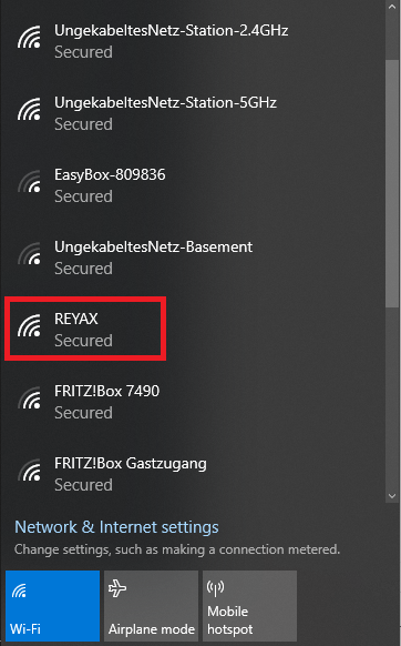
> "OK\r\n"Now, the Access Point can be started. If the start was successful, the access point should show up in the list of accessible WLAN networks:
< "at+rsi_join=REYAX,0,2\r\n"
> "OK<GO status>\r\n"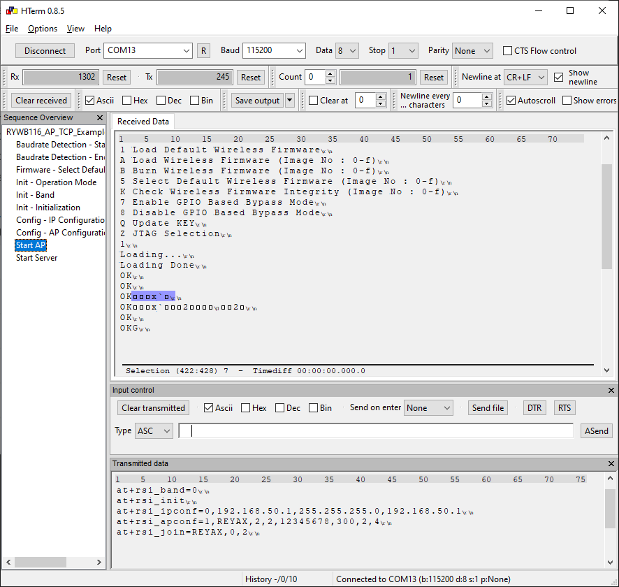
As a final step, we start a TCP server on port 5001 where up to 5 clients are able to connect to:
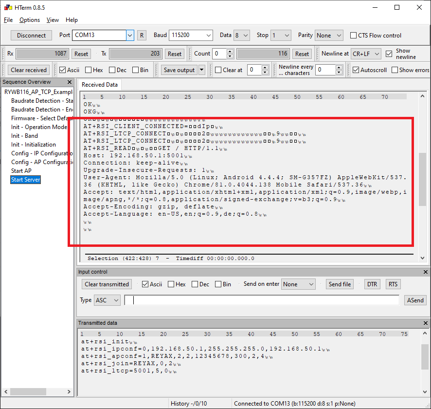
< "at+rsi_ltcp=5001,5,0\r\n"When we have sent the command, we can use our PC or mobile device, connect to the WLAN “REYAX”, open up a web browser and enter the URL “http://192.168.50.1:5001”. If we do so, the module will send the text of the HTTP Request.
And that’s it!
Video tutorial

[…] the first part of this guide, it has been shown how to start an WiFi access point and a TCP server with an RYWB116 module (RYWB116_Lite breakout board). Initially, I planned to explain in the second part how to use an RYWB116_Lite breakout board in […]
[…] module, e.g. to have a look in some module settings. As in my other tutorials about Reyax modules ( RYWB116, RYBI080, and RYS8830), a “USB-to-TTL” device is used to establish a connection between […]