
Recently, I got my hands on a Grove Beginner Kit for Arduino. Although I have heard of the Grove ecosystem before, it has been the first time I actually tried it out.
Equipment:
What is Grove?
Grove is kind of a electronics ecosystem coming from Seeed Studio. Probably, the primary target audience of Grove are beginners that are looking for something more simple than starting with a plain Arduino and a set of sensor/actuator modules from the shelf. If you go for a plain Arduino and a set of modules, you are sometimes facing the problem that you do not know how to wire a module to an Arduino. Moreover, if you are searching the Internet for a specific piece of code for your module, it can happen that it simply does not work. Either it has not been the right piece of code, the module version is not exactly the same, or the manufacturer changed something without changing the name or version of the module.
On the one hand, I think struggling around with such problems (and solving them) helps to get a better understanding of electronics. On the other hand, I can really share the pain when reading my readers’ comments or mails that the code or wiring is not working because it is not the same module. If you are a beginner and do not know how to proceed then, this can become very frustrating. With Grove, all modules come from the same vendor — or are at least a little bit more standardized than ‘normal modules’. So you are running less likely in wiring or code mismatch problems.
What is Grove on a more technical level?
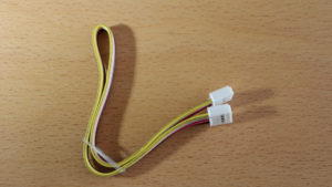
The main components of the Grove ecosystem are the Grove base units, e.g. a Grove-compatible Arduino Uno, that are connected to Grove modules. Grove base units and modules come with special connectors, which have 4 pins. Base units and modules can be wired by Grove cables, which have 4 wires and fit on the special connectors. Depending of the specific module, the cable is used for a different type of connection (Analog, Digital, UART or I2C). In the following you find the pin/wiring setup that can be found on the Grove Beginner Kit:
| Pin / Wire | Function | Comment |
| Pin 1 / Yellow | SIG | Analog signal |
| Pin 2 / White | NC | Normally closed / unused |
| Pin 3 / Red | VCC | 5V/3.3V voltage supply for module |
| Pin 4 / Black | GND | Ground |
| Pin / Wire | Function | Comment |
| Pin 1 / Yellow | SCL | I2C Clock |
| Pin 2 / White | SDA | I2C Data |
| Pin 3 / Red | VCC | 5V/3.3V voltage supply for module |
| Pin 4 / Black | GND | Ground |
So, in a nutshell: Grove is a ecosystem with ‘standardized’ base units and modules + a simplified wiring scheme including special connectors and wires.
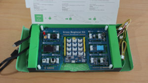
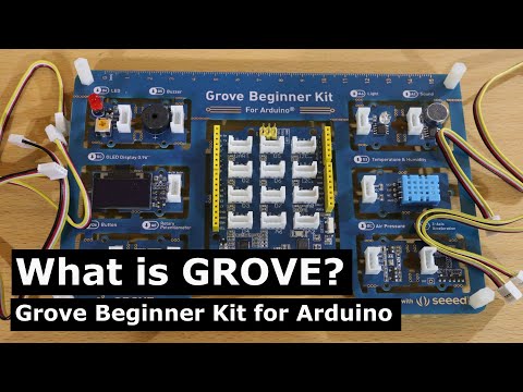
Grove Beginner Kit for Arduino
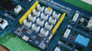
The Grove beginner kit is a box (yes, the packaging is part of the kit) with a Grove-compatible Arduino and 10 modules integrated on a single board. ‘Integrated’ means that you do not need the Grove cables, since all modules are already ‘PCB-wired’ to the Arduino. The idea is that you are free to choose whether you want the board as it is or, alternatively, ‘break out’ the modules and then you need the wires to get them connected again. As I like the concept of having an all-in-one-board, I just left everything as is. Well noted is that the beginner kit is ready-to-use, besides some Grove wires it comes also with a micro USB cable. In addition, Seeed Studio published a PDF with about 12 code examples for the beginner kit.
In the following, an example is provided that is not part of the PDF. Instead, I created a new example that makes use of multiple modules at the same time. I chose such an example, as I receive a lot of messages from beginners that are often struggling with combining multiple modules.
Example: Light Intensity Alarm
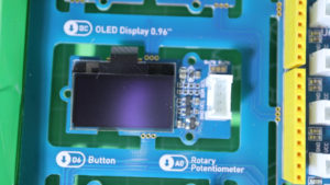
The idea of this example is to control the LED and Buzzer based on how much light is detected by the Light sensor. The higher the amount of light, the higher the frequency of the LED blinking and the Buzzer turning on/off. Moreover, the Buzzer is only active if the Button is pressed. The OLED display shows the currently detected light and the corresponding frequency used for the LED and Buzzer module.
As all modules are already connected to the Arduino, we can directly start with the programming. The code requires an external library (U8g2) which is required to control the display module (Grove OLED Display 0.96″). When I was playing around with my beginner kit, I also used some other libraries for the display module. But in the end, the U8g2 worked best and is also used in the official examples provided by Seeed Studio.
Regarding the light sensor values, I chose 750 as a maximum value as it was a good fit to my lighting conditions. Here, you are totally free to use a different maximum value.
/*
MIT License
Copyright 2020 Michael Schoeffler (mschoeffler.de)

Permission is hereby granted, free of charge, to any person obtaining a copy of this software and associated documentation files (the "Software"), to deal in the Software without restriction, including without limitation the rights to use, copy, modify, merge, publish, distribute, sublicense, and/or sell copies of the Software, and to permit persons to whom the Software is furnished to do so, subject to the following conditions:
The above copyright notice and this permission notice shall be included in all copies or substantial portions of the Software.

THE SOFTWARE IS PROVIDED "AS IS", WITHOUT WARRANTY OF ANY KIND, EXPRESS OR IMPLIED, INCLUDING BUT NOT LIMITED TO THE WARRANTIES OF MERCHANTABILITY, FITNESS FOR A PARTICULAR PURPOSE AND NONINFRINGEMENT. IN NO EVENT SHALL THE AUTHORS OR COPYRIGHT HOLDERS BE LIABLE FOR ANY CLAIM, DAMAGES OR OTHER LIABILITY, WHETHER IN AN ACTION OF CONTRACT, TORT OR OTHERWISE, ARISING FROM, OUT OF OR IN CONNECTION WITH THE SOFTWARE OR THE USE OR OTHER DEALINGS IN THE SOFTWARE.
*/

/*
Explanation: The idea of this example is to control the LED and Buzzer based on how much light is detected by the Light sensor.
The higher the amount of light, the higher the frequency of the LED blinking and the Buzzer turning on.
Moreover, the Buzzer is only active if the Button is pressed.
The OLED display shows the currently detected light and the corresponding frequency used for LED and Buzzer.
*/

#include <U8x8lib.h> // Header file is part of the required U8g2 library. Arduino IDE: Install U8g2 library --> Go to "Tools", then "Manage Libraries.".

#define LED 4 // LED is on Digital Pin 4 of Grove Beginner Kit
#define Buzzer 5 // Buzzer is on Digital Pin 5 of Grove Beginner Kit
#define Button 6 // Button is on Digital Pin 6 of Grove Beginner Kit
#define Light A6 // Light sensor is on Analog Pin 6 of Grove Beginner Kit

U8X8_SSD1306_128X64_ALT0_HW_I2C u8x8(/* reset=*/ U8X8_PIN_NONE); // Part of the initalization of the OLED Display 0.96"

bool toggle = false; // This variable represents the toggle state of the LED and Buzzer

void setup() {
  pinMode(LED, OUTPUT); // LED is an output
  digitalWrite(LED, LOW); // LED is set to zero --> "out"

  pinMode(Buzzer, OUTPUT); // Buzzer is also an output
  digitalWrite(LED, LOW); // Buzzer is set to zero --> "out"

  pinMode(Button, INPUT); // Button is an input
  pinMode(Light, INPUT); // Light sensor is also an input

  u8x8.begin(); // Display is now ready to use
  u8x8.setFlipMode(1); // Technically, the display is mounted upside down on the Grove module. Therefore, we flip it.
  u8x8.setFont(u8x8_font_chroma48medium8_r); // font type
}

void loop() {
  int light_measured = analogRead(Light); // Light is measured
  int frequency = map(light_measured, 0, 750, 1000, 10); // Amount of light is converted to the turn on/off frequency of the LED (and buzzer).
  // Additional explanation: No light (sensor value: 0) will switch on/off the LED each 1000ms
  // A lot of light (sensor value => 750) will  switch on/off the LED each 10ms ("LED starts flickering")

  u8x8.clear(); // Display is cleared in each step to remove old values

  u8x8.setCursor(0, 0); // Cursor of display is set to first position (first row)
  String light = "Light: " + String(light_measured); // String with measured light value
  u8x8.print(light.c_str()); // string is printed to display

  u8x8.setCursor(0, 1); // Cursor is set to the second row
  String freq = "Frequency: " + String(frequency);
  u8x8.print(freq.c_str());

  digitalWrite(LED, toggle); // The LED is turned on/off based on the current value of the toggle variable
  if (digitalRead(Button) == HIGH) { // if the button is pressed, some additional code is executed (Buzzer)
    digitalWrite(Buzzer, toggle);  // Buzzer get's also a toggle value. This will result in a short audible 'click' (synchronized with the LED status)
  }
  toggle = !toggle; // Toggle value is inverted; E.g. if toggle is LOW, the new value will be HIGH.

  delay(frequency); // The code is executed again after a waiting time that corresponds to the calculated frequency representation.
  // Additional remark: The previous line is a minor weakness of the code, if the amount of light/frequency is low, the reaction time of the programm is also low as it is in 'delay' state
}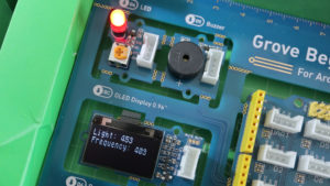
When the code is compiled and transferred to the Arduino on the Beginner Kit, the LED should start blinking based on the amount of light. For example, if you hold your hand over the Light sensor (so that no light is captured at all), the LED should blink very slowly. If you hold the beginner kit towards the sun (or another light source), the LED should start blinking much faster. The Display module should show the current values of the light sensor as well as the calculated frequency. If you press the button, the Buzzer should make clicks in the same pattern as the LED blinks.
If you read the code carefully, you might have recognized that the frequency implementation is not perfect. The frequency pattern is implement with a delay function which is a drawback for the program’s reaction time if the amount of light changes form little to a lot. Nonetheless, I chose this implementation as I thought it is a good trade-off between functionality and understandability of the code.
Overall, I think the Grove ecosystem is a good idea and well suited for people who do want to start as smoothly as possible. Naturally, in comparison to using a ‘normal’ Arduino and modules, the prices of Grove components are a bit higher. But in return, you get a full documentation for each module from Seeed Studio + an ‘implicit guarantee’ that the module will work with your base unit and code example. Moreover, the quality of the Grove components is very good — at least what I have seen from the modules on my beginners kit.
Video
Additional information
- There exists a possibility to make a custom-made Grove board with Geppetto. Have a look at Seeedstudio’s wiki article for more information, if this is of interest for you.
[…] this article, I want to give a short overview to the new kit. Moreover, I want to compare it to the Grove Beginner Kit that I reviewed a few month ago, since both kits look very much alike. And in addition, I want to elaborate on whether it can also […]