
This tutorial shows how to establish a serial connection connection from an Arduino to another Arduino. Each Arduino has a tact switch and an LED. If an Arduino’s tactile switch is pressed, the LED of the other Arduino will be turned on.
List of materials (each item of this list is needed 2x):
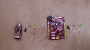
In order to demonstrate the Arduino-to-Arduino communicaten two different types of Arduinos are used. The first Arduino is an Seeeduino Nano, which is a variant that is compatible to the Arduino Nano. The second Arduino is an Seeeduino V4.2 which is fully compatible to the Arduino Uno (see https://www.seeedstudio.com/seeeduino-boards-c-987.html for more information). Both Arduinos will send only on of two bytes: Either ‘0’ or ‘1’. If ‘0’ has been transmitted, the LED will be turned off. If ‘1’ has been transmitted, the LED will be turned on.
Wiring
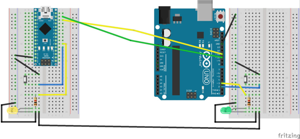
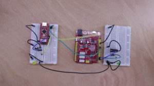
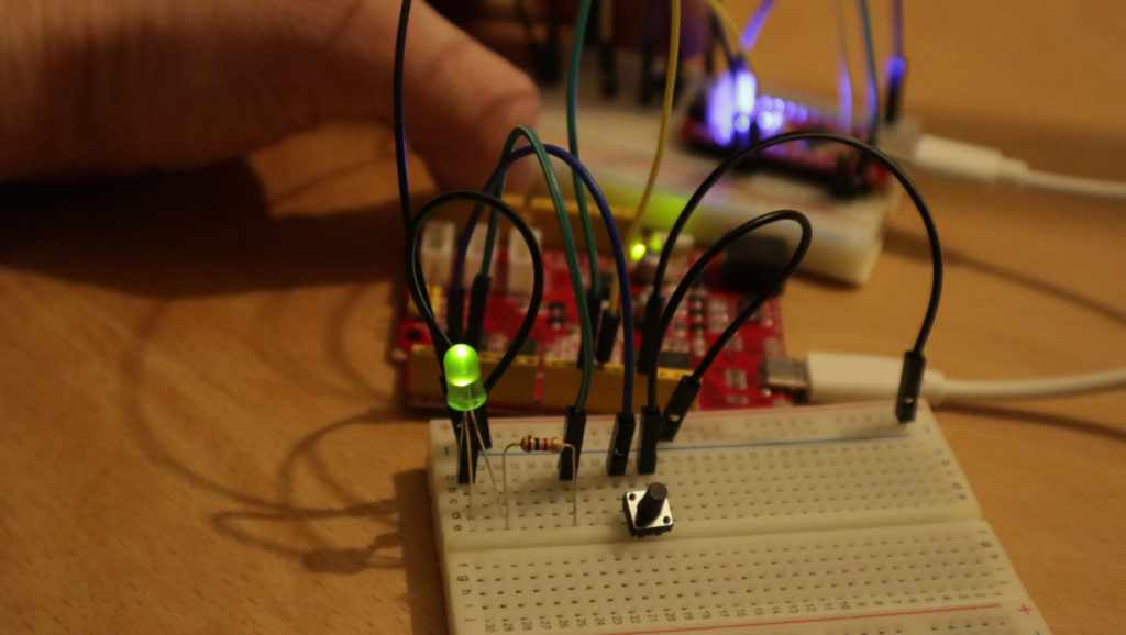
Both Arduino setups have the basically the same wiring: a tact switch, an LED and a 1k resistor is added to a breaboard. The tact switch is wired to GND and two digital pin #2. The LED is wired to GND and the 1k resistor. The resistor is wired to digital pin #3. The serial connection requires three wires: for GND, receive and transmit. The receive wire is connected to digital pin #10. The transmit wire is connected to digital pin #11. In order to make the serial connection work, the receive wire of one Arduino is connected to the transmit wire of the other Arduino. The GND wire might not be needed, e.g. as both Arduinos probably share the same GND signal when powered from the same power supply. Nonetheless, it has been added to the wiring diagram for the sake of completeness.
Source code
First, the pins for the tact switch (INPUT_PULLUP) and LED (OUTPUT) are set up. Then, the serial connection is started. In the loop function, it is checked whether a byte was received from the serial connection. The digital output is set to the received byte: Either ‘0’/false to turn off the LED or ‘1’/true to turn it on. Next, the current status of the tact switch is sent. ‘0’ is sent to the other Arduino, if the tact switch if not pressed. Otherwise, ‘1’ is sent. At the end of the loop function, a delay of 250ms is added.
// (c) Michael Schoeffler 2020, http://www.mschoeffler.de

/*
 * This program is part of a tutorial that shows how to communicate from an Arduino to another Arduino via a serial connection.
 * The status of a tact switch is sent to the other Arduino. If the switch is pressed, an LED is turned on.
 * This program has to be transferred to both Arduinos in order to make the application work.
 */

#include <SoftwareSerial.h>

const int IN_TACT_SWITCH = 2; // input pin for tactile switch
const int OUT_LED = 3; // output pin for LED

SoftwareSerial sserial(10,11); // receive pin=10, transmit pin=11


void setup() {
  pinMode(IN_TACT_SWITCH, INPUT_PULLUP); // set the LED pin to input pullup mode
  pinMode(OUT_LED, OUTPUT); // set the LED pin to output mode
  sserial.begin(9600); // start serial connection
}

void loop() {

  // receive
  if (sserial.available() > 0) {
    byte incomingByte = 0;
    incomingByte = sserial.read();
    if (incomingByte != -1) {
      Serial.print(incomingByte);
      digitalWrite(OUT_LED, incomingByte); // switch LED on or off
    }
  }

  // send
  sserial.write(!digitalRead(IN_TACT_SWITCH)); // Tact switch (used in the corresponding tutorial) is inverted. Therefore, inverted status is sent to other Arduino

  delay(250); // delay required to avoid flooding the other Arduino ("DoS attack")
}
Deployment
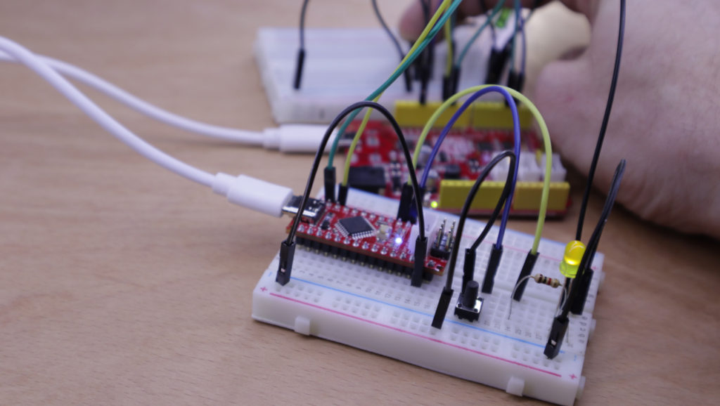
The source code has to be transferred to both Arduinos (= both Arduinos have the same very same code). If everything has been executed correctly, an Arduino’s LED is switched on, if the tact switch of the other Arduino has been pressed.
Video tutorial

Looks like a very easy and straightforward bi-directional serial communication solution. I have been trying to apply this program to two Seeeduino XIAO boards but I have had no luck so far porting the program over to the XIAO. Any help that you can offer would be greatly apricated.