
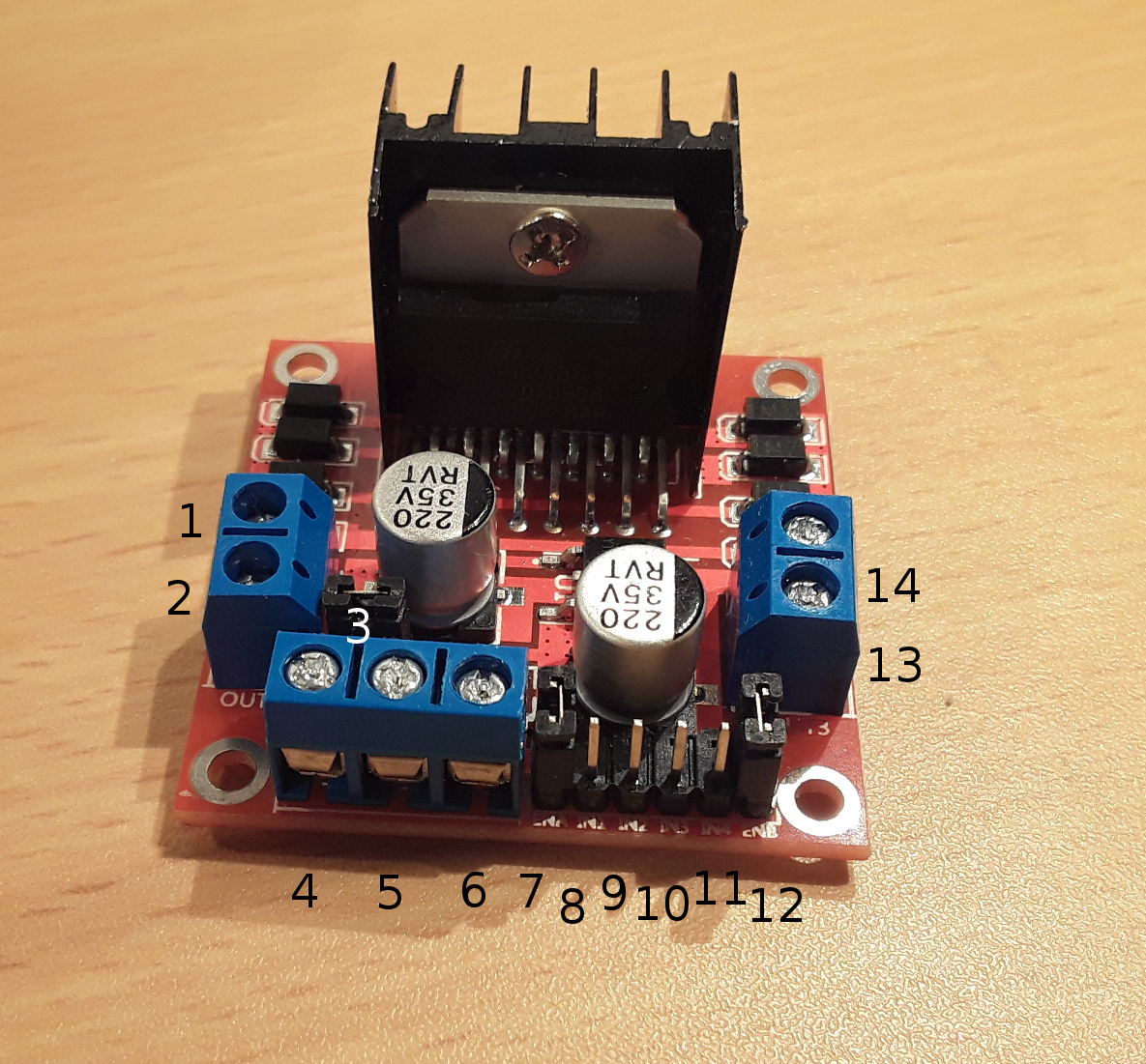
1: + (DC motor 1)
2: – (DC motor 1)
3: If jumper enabled, 5V output on pin 6(e.g. for driving an Arduino)
4: Vcc of motor voltage supply
5: GND
6: 5V output, if jumper enabled
7 (ENA): One of Arduino’s PWM pins can be connected (to the lower pin) to control the speed of motor 1. If the jumper is enabled, motor 1 will run on full speed.
8 (IN1): Controls direction of motor 1
9 (IN2): Controls direction of motor 1
10 (IN3): Controls direction of motor 2
11 (IN4): Controls direction of motor 2
12 (ENB): One of Arduino’s PWM pins can be connected (to the lower pin) to control the speed of motor 2. If the jumper is enabled, motor 2 will run on full speed.
13: + (DC motor 2)
14: – (DC motor 2)
In order to control a DC motor with the Arduino Uno, a motor controller module is required. Such module is needed, for various reasons: For example, the Arduino can’t power DC motors with a voltage higher than 5V. However, many DC motors need more than 5V, especially when they are supposed to move on full speed. Moreover, most DC motors need more power than the Arduino could provide. In this tutorial, the L298N Dual Motor Controller is used to control a single DC motor with the Arduino Uno. The L298N module can also be used to control two motors with different directions and speeds.
List of materials:
| Arduino Uno | |
| Jumper wires | |
| Jumper wire clamps | |
| Breadboard | |
| L298N module | |
| DC motor | |
| USB power boost 5V-to-9V (optional) | |
| DC power jack socket (optional) |
Pin Layout:
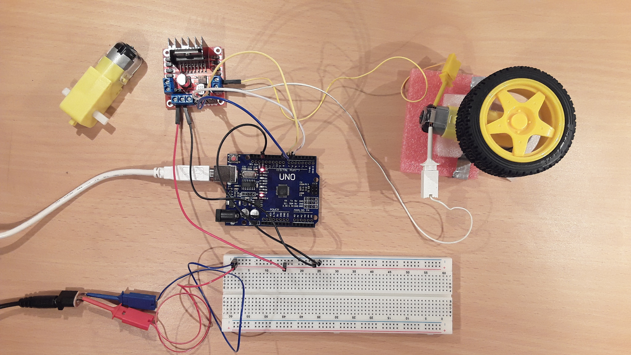
In order to power the DC motor, two voltage supplies with different voltages are needed. The used DC motor has an operating voltage of 3V up to 12V. As the L298N module drops the voltage by more than 2V, the 5V voltage supply (USB) of the Arduino can’t be used. Therefore, a second voltage supply of 9V is used. In this tutorial, a USB Power boost (5V-to-9V) is used in combination with a DC power jack socket. Then, the power jack socket is connected to the breadboard. The breadboard’s “+” line (Vcc) is connected to pin 1 of the L298N module. The breadboard’s “-” line (GND) is connected to pin 2 of the L298N module. It is important that the L298N module and the Arduino share the same GND. Therefore, the breadboard’s “-” line is also connected to one of the Arduino’s GND pins.
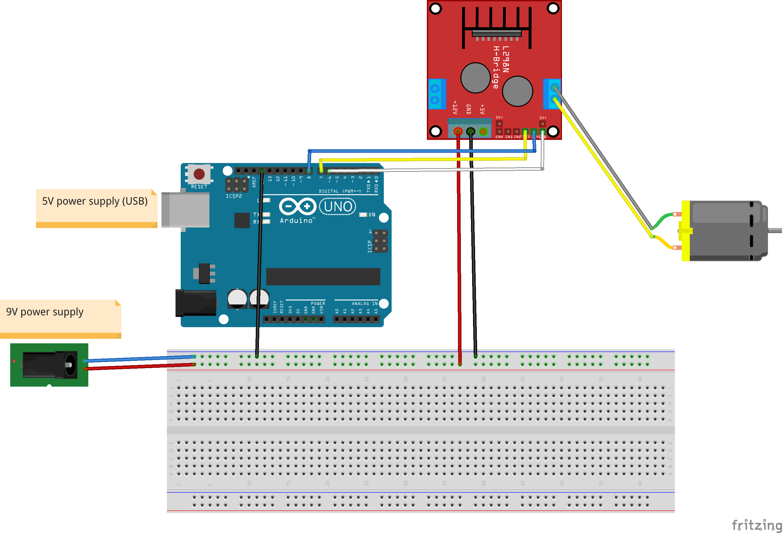
The Arduino’s pin 6 is connected to the ENB pin of the module. This connection is used to control the speed of the motor and, therefore, using one of the Arduino’s PWM-enabled pins is required. Then, the Arduino’s pins 7 and 8 is connected to the module’s pins IN3 and IN4, respectively. These pins are used to control the direction of the DC motor (IN3=HIGH/IN4=LOW or IN3=LOW/IN4=HIGH).
As a final step, the module’s output pins for the second motor (pin 13 and 14) are connected to the DC motor.
Example source code:
This source code drives the motor in four different states: Forward in slow and fast mode as well as backward in slow and fast mode. The functions slow() and fast() write an analog value to the PWM pin that is connected to ENB. The higher the value (0 to 255), the higher the speed of the motor. Please note, that the motor will not work if the values are too low.
In the loop function, the motor is driven forward in slow mode for five seconds. Naturally, the direction of the motor also depends on the direction you mounted the motor as well as on how you connected the motors pin to the module’s pins 13 and 14. Then, the motor drives in fast mode for 5 seconds. Next, the motor changes the direction and is driven in slow mode for 5 seconds as well as in fast mode for 5 seconds.
// (c) Michael Schoeffler 2016, http://www.mschoeffler.de

const int enb = 6; // PWM pin 6
const int in3 = 7;
const int in4 = 8;

void setup() {
  pinMode(in3, OUTPUT);
  pinMode(in4, OUTPUT);
  pinMode(enb, OUTPUT);
}

void slow() {
  analogWrite(enb, 128);
}

void fast() {
  analogWrite(enb, 255);
}

void loop() {
  digitalWrite(in3, LOW);
  digitalWrite(in4, HIGH);
  slow();
  delay(5000);
  fast();
  delay(5000);
  // change of direction
  digitalWrite(in3, HIGH);
  digitalWrite(in4, LOW);
  slow();
  delay(5000);
  fast();
  delay(5000);
}
Video Tutorial
Side Notes:
- The L298N module can also be used to drive stepper motors.
- You can also drive more than two motors. Just share the pins 13 and 14 (or 1 and 2) with multiple motors. If multiple motors share the same pins they will also share the direction and speed.
- The module’s pins 7 to 12 (ENA, IN1, IN2, IN3, IN4 and ENB) work with TTL logic levels (5V). Therefore, we can set the values directly from the Arduino if the same GND is shared.
Folks, please stop promoting that steam punk machine called L298N just because everyone else says so and you are too lazy to understand, that it is totally outdated! It’s not the go to thing at all.
look up DRV8833 and DRV8871 for example.