
Typically, servo motors are a combination of four things: a conventional DC motor, a set of gearings, a potentiometer, and a control circuit. Among these four things, the potentiometer acts as a position sensor. As a result, servo motors can be controlled very precisely. In particular, a command can be sent to the servo so that the servo’s shaft rotates to a specific position. However, the disadvantage of these servos is that the rotation range is limited (e.g. between 0 and 180 degrees). Nonetheless, servo motors are very useful if a projects requires a motor with a precise control and awareness of its current position.
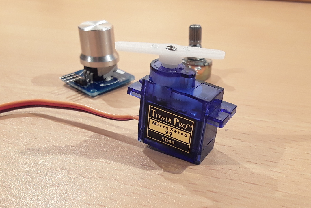
The SG90 is such a servo motor that can rotate approximately 180°. Moreover, is is very small and lightweight (Weight: 9g; Dimension: 22.2 x 11.8 x 31 mm). In this tutorial, it is shown how to control the SG90 servo motor. In order to control the motor, a so-called rotary angle sensor module is used. This module is nothing more than a conventional potentiometer combined with a knob. Therefore, it can be simply replaced by almost any potentiometer, since it is used here only for convenience reasons.
List of materials:
| Arduino Uno | |
| Jumper wires | |
| Mini breadboard | |
| Rotary angle sensor | |
| Potentiometer (in alternative to the rotary angle sensor) |
Pin layout:
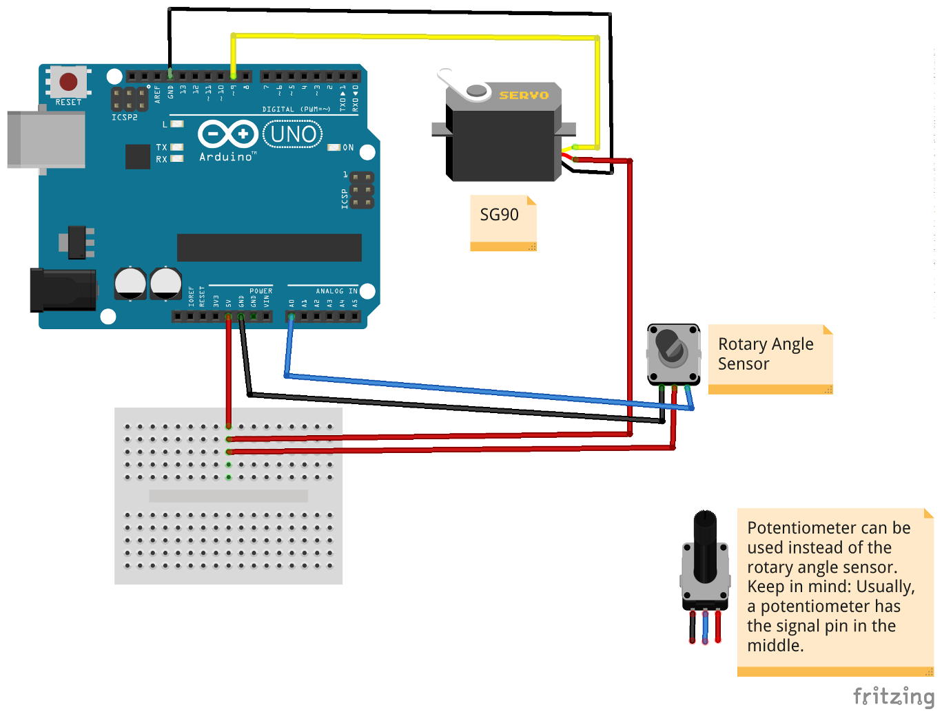
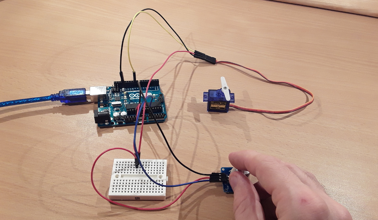
First, we connect the SG90 servo motor to the Arduino Uno. Both, the servo and the rotary angle sensor need a voltage supply. Since the Arduino Uno has only one 5V pin, we use a breadboard to split the 5V signal. The Arduino’s 5V pin is connected to a breadboard. Then, the servo’s red wire is connected to the breadboard (same column as previous pin). Next, the brown wire of the SG90 must be connected to one of the Arduino’s GND pins. In order to control the SG90 servo, PWM signals (Pulse Width Modulation) must be sent through the yellow wire. In this tutorial, digital pin 9 of the Arduino is used for this task and, therefore, wired to the SG90’s yellow pin.
Following, we have to wire the rotary angle sensor to the Arduino. The sensor’s left pin is the ground which must be connected to one of the Arduino’s GND pins. The pin in the middle is the VCC pin, which must be connected to breadboard (same column as the other two pins). Finally, the sensor’s SIG pin must be connected to one of the Arduino’s analog input pins. Here, I make use of analog pin A0. If a potentiometer is used instead of the rotary angle sensor: Typically, the outer pins of the potentiometer must be connected to the power supply (GND and 5V pin of the Arduino). The pin in the middle is the signal pin which corresponds to the sensor’s SIG pin and must be connected to an analog input pin (e.g. A0).
Example source code:
Luckily, the Arduino IDE has already a built-in servo library. In order to use this library, we have to include its header file. Next, we define two pins: digital pin 9 for the servo motor and analog pin A0 for the rotary angle sensor (or potentiometer). Then, a servo object is created that will be used to control the servo motor. Subsequently, two variables are defined. The first one is used to store the values retrieved from the sensor/potentiometer. The second variable is the rotation value that will be sent to the servo motor.
In the setup function, we attach digital pin number 9 to the servo object. The servo object is now fully initialized and ready to control the servo.
In the loop function, we read the analog value of the rotary angle sensor’s knob (or value of the potentiometer). As the Arduino’s analog-to-digital converter will map the voltage to values between 0 and 1023, we have to remap these values to an rotary angle value that is supported by our servo motor. Since the SG90 supports approximately 180°, we map the value two values between 5° and 175°. According to my experience, the SG90 does not sound very “healthy”, if the full range of 180° is used. Therefore, we subtracted 10° in order to avoid damaging our servo motor. After calling the map-function, the resulting value is used to let the servo turn its shaft. At the end of the loop function, we add a delay of 20ms to give the servo some time to turn its shaft.
// (c) Michael Schoeffler 2017, http://www.mschoeffler.de

#include "Servo.h"

#define PIN_SERVO 9
#define PIN_KNOB A0

Servo servo; // creates servo object to control the SG90 servo

int value_knob = 0; // will be used to store the value of the potentiometer/knob
int value_servo = 0; // will be used to control the servo => should be between 5 and 175 degrees

void setup()
{
  servo.attach(PIN_SERVO); // assigns pin 9 to the servo object
}

void loop()
{
  value_knob = analogRead(PIN_KNOB); // reads value of the knob/potentiometer. Return value will be between 0 and 1023.
  value_servo = map(value_knob, 0, 1023, 5, 175); // will map knob value range to servo value range
  servo.write(value_servo); // shaft of servo will start to rotate. value_servo is interpreted as an absolute position.
  delay(20); // give servo some time to rotate
}
After transferring the program to the Arduino Uno, you should be able to rotate the servo’s shaft.
Video tutorial:
I’ve just bought a few of the SG90 servos off of Ebay and will be checking them out soon, prototyping sounds too posh but, despite the fact that all the sellers quote specs at me I could not find any info regarding pinouts. This may seem very simple but when you consider it, well, the choosen colour scheme doesn’t make it obvious. However, no such messing around here. I have found your instructions to be clear and concise, most of all, complete with cable colour designation info. Many thanks.
Best Regards Terry Bruce.
Well guided video to understand how to drive servo motor. But seems difficult to drive motor with arduino supply itself. Anyway it helps me to understand my issue to driving servo motor. I understood it cant be drive without external power supply with 9 to 12V. after connecting with external power supply servo motor start running smoothly.
very useful video had a lot of help