
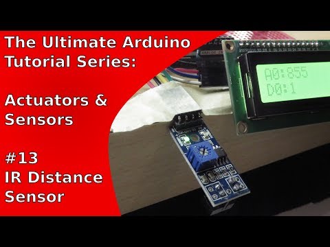
In this tutorial, it is shown how to use an IR distance sensor with an Arduino Uno. The todays sensor comes in many names: MH Sensor Series, KY-033 (variant with 3 pins), TCRT5000, etc. Moreover, it is often advertised as IR distance sensor, line tracing sensor or line tracking sensor.
In addition to the IR distance sensor, this tutorial makes use of an LCD module called “LCM1602 IIC V1” which is utilized to show sensor values. The main advantage of the LCM1602 IIC V1 is that it is very easy-to-use. For example, it can be controlled by setting up an I2C connection.
List of materials:
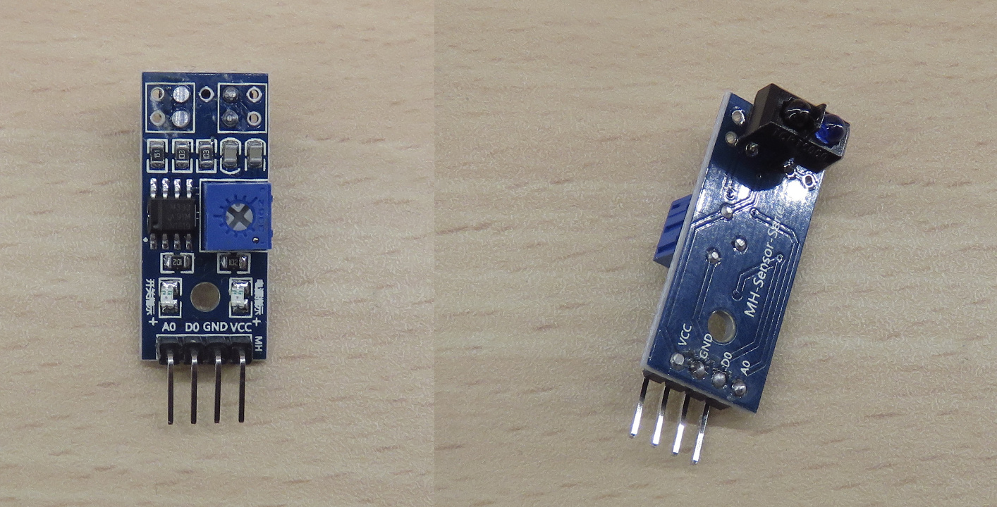
Remark: Some variants of the module type, such as the KY-033, have only three pins. Typically, the A0 pin is missing. Moreover, the D0 pin is often labeled as S. If you own such a variant, this tutorial is still of use to you. Just ignore the part related to the A0 pin.
Pin layout:
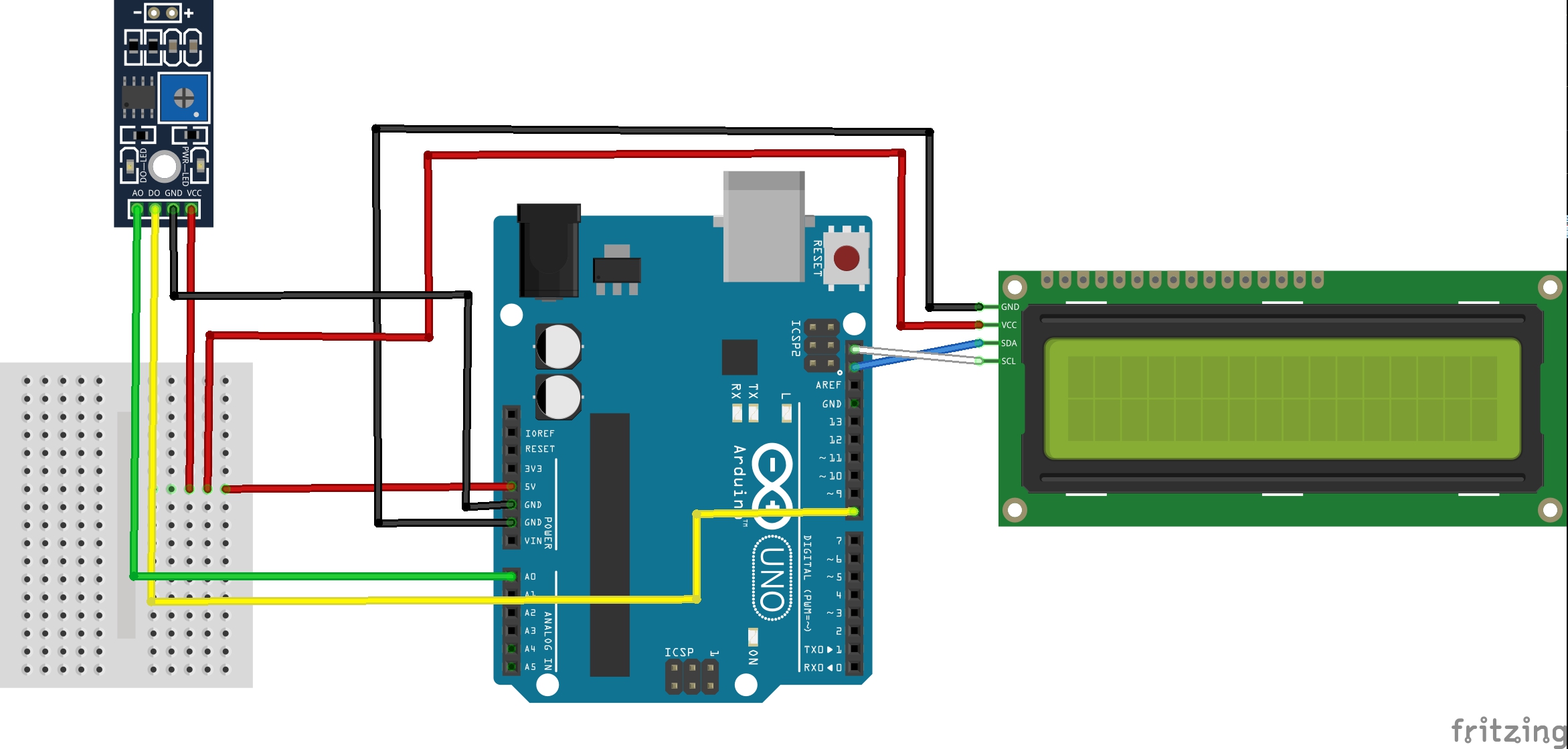
The IR sensor and the LCM1602 module have only four pins. The GND pins of both modules must be connected to the Arduino’s GND pins. The same applies to the VCC pins which must be connected to the Arduino’s 5V pin. As the Arduino Uno has only a single 5V pin, a mini breadboard is used to “split” the 5V pin. Next, the A0 and D0 pin of the IR sensor must be connected to the Arduino. The A0 pin is the raw analog value (0-1023) of the measured distance between the sensor and an obstacle. In this tutorial, A0 is connected to the Arduino’s A0 pin. The D0 pin is a digital pin that goes to HIGH state if the analog value is greater than or equal to a specific threshold. The threshold can be adjusted by the blue trimpot of the IR distance sensor. Here, D0 is connected to the Arduino’s pin 8.
As a last step, the LCM1602 module’s SDA and SCL pins must be connected to the corresponding SDA and SCL pins of the Arduino Uno.
Example source code
// (c) Michael Schoeffler 2017, http://www.mschoeffler.de
#include <Wire.h>
#include <LiquidCrystal_I2C.h>
LiquidCrystal_I2C lcd(0x27, 2, 1, 0, 4, 5, 6, 7, 3, POSITIVE); // initializes the LCM1602 IIC V1 (LCD module)
// 0x27 is the I2C address. This address might be different.
const int IN_A0 = A0; // analog input
const int IN_D0 = 8; // digital input
void setup() {
pinMode (IN_A0, INPUT);
pinMode (IN_D0, INPUT);
lcd.begin(16, 2); // begins connection to the LCD module
lcd.backlight(); // turns on the backlight
}
int value_A0;
bool value_D0;
void loop() {
value_A0 = analogRead(IN_A0); // reads the analog input from the IR distance sensor
value_D0 = digitalRead(IN_D0);// reads the digital input from the IR distance sensor
lcd.setCursor(0, 0); // sets the cursor of the LCD module to the first line
lcd.print("A0:");
lcd.setCursor(3, 0); // sets the cursor of the LCD module to the fourth character
lcd.print(value_A0); // prints analog value on the LCD module
lcd.setCursor(0, 1); // sets the cursor of the LCD module to the first line
lcd.print("D0:");
lcd.setCursor(3, 1); // sets the cursor of the LCD module to the fourth character
lcd.print(value_D0); // prints digital value on the LCD module
delay(1000);
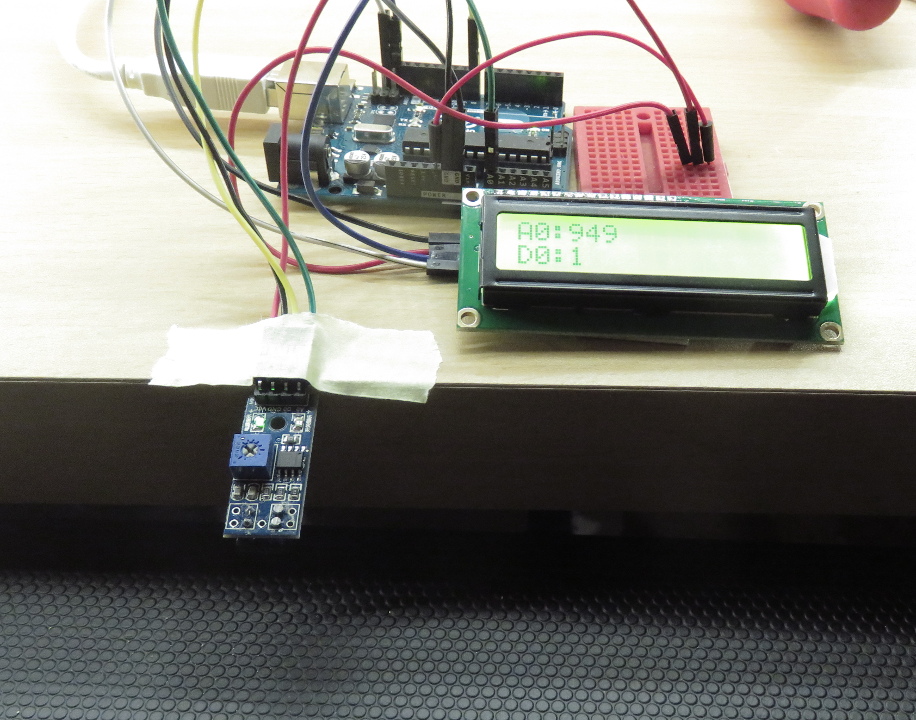
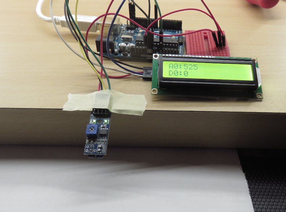
}If the code has been compiled and transmitted to the Arduino Uno, the LCD module should show the distance between the IR distance sensor and an obstacle. Keep in mind that the distance is indicated by a analog value between 0 and 1023. Unfortunately, it is very challenging to convert the analog value to a metric unit of length, such as meter or centimeter. The reason is that the measured analog value is strongly influenced by the obstacle’s material. For example, black surface does reflect far less light than white surface. As a consequence, the measured analog value will differ. Interestingly, this characteristic can be used in order to use the IR distance sensor as a “black or white” detector. This application can often be found in “car assembly kits” where multiple IR sensors are mounted on the undercar. As a result, the car is capable of following a black line that is drawn on white ground.
The following pictures show distance measurements with black and white material. Although the distance is about the same, the measured analog value (A0) differs strongly:
Video tutorial
hi there ;
i had some problems with this sensor, i’m using it as a line tracker sensor and i want to know if there is limits for the distance that should be between the ground (black and white) and the sensor ?
thanks.
In my experience, there should be at least 2-3cm between the sensor and the obstacle.
Hello,
I working on smart car parking by using this IR Sensor, Arduino, servo and 7-segments display. I want to add the sensor to track the car and 7-segments display to show how many parking avaliable ( limit 6 parking) and servo to allow or deny the car to access the parking. So, How this project will done ? I need your help please
Regards,
hola no tengo un error a cargar el programa
Arduino:1.8.6 (Windows Store 1.8.14.0) (Windows 10), Tarjeta:”Arduino/Genuino Uno”
ir_prueba:4:53: error: ‘POSITIVE’ was not declared in this scope
LiquidCrystal_I2C lcd(0x27, 2, 1, 0, 4, 5, 6, 7, 3, POSITIVE );// initializes the LCM1602 IIC V1 (LCD module)
^
exit status 1
‘POSITIVE’ was not declared in this scope
Este reporte podría tener más información con
“Mostrar salida detallada durante la compilación”
opción habilitada en Archivo -> Preferencias.
LiquidCrystal_I2C lcd(0x27,16,2);
// cris saez
#include
#include
LiquidCrystal_I2C lcd(0x27,16,2); // initializes the LCM1602 IIC V1 (LCD module)
// 0x27 is the I2C address. This address might be different.
const int IN_A0 = A0; // analog input
const int IN_D0 = 8; // digital input
void setup() {
pinMode (IN_A0, INPUT);
pinMode (IN_D0, INPUT);
Wire.begin();
lcd.begin(16, 2); // begins connection to the LCD module
lcd.clear();
lcd.backlight(); // turns on the backlight
}
int value_A0;
bool value_D0;
void loop() {
value_A0 = analogRead(IN_A0); // reads the analog input from the IR distance sensor
value_D0 = digitalRead(IN_D0);// reads the digital input from the IR distance sensor
lcd.setCursor(0, 0); // sets the cursor of the LCD module to the first line
lcd.print(“A0:”);
lcd.setCursor(4, 0); // sets the cursor of the LCD module to the fourth character
lcd.print(value_A0); // prints analog value on the LCD module
lcd.setCursor(0, 1); // sets the cursor of the LCD module to the first line
lcd.print(“D0:”);
lcd.setCursor(4, 1); // sets the cursor of the LCD module to the fourth character
lcd.print(value_D0); // prints digital value on the LCD module
delay(1000);
}
Hi Michael,
where did you find that nice Fritzing part for the TCRT5000 component? I can’t find it anywhere…
Thanks, Tobi
hello, sir please tell me how to connect my wire into GND(ground)?