
In this tutorial, it shown how to build an optical barrier. The barrier detects any movement between the sender and the receiver. The sender is a laser module (Keyes KY-008) that emits red light (wavelength: 650nm). The laser detector/receiver is an unnamed module that returns either a LOW signal or a HIGH signal (no “analog values” in between).
List of materials:
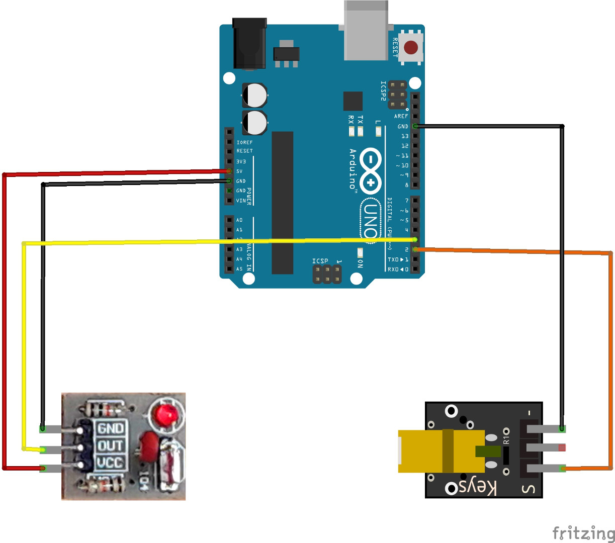
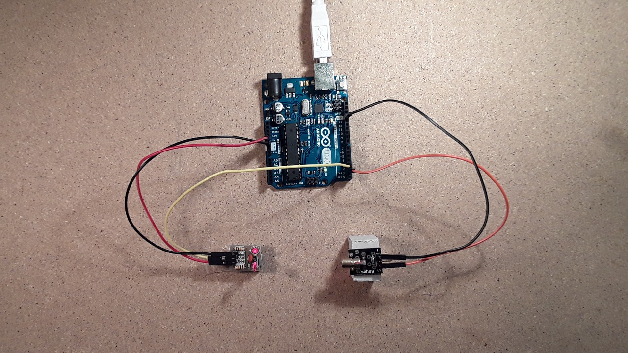
How to connect the laser module and laser detector to the Arduino?
The laser module has three pins. Only two pins are used: The “-” pin is connected to one of the Arduino’s GND pins. The “S” pin of the laser module is connected to the Arduino’s pin “2”. Therby, the laser can be switched off or on by sending either a LOW signal or a HIGH signal. The detector module has also three pins. The module’s “VCC” pin is connected to the Arduino’s “5V” pin and the GND of the module is connected to the Arduino’s GND. Lastly, the signal pin”OUT” of the module is connected to pin “3”.
How to program the light/optical barrier?
First, the pin values for the laser and the receiver are initialized. Next, the laser pin is set to OUTPUT mode and the receiver pin is set to INPUT mode. Then, the laser is switched on by setting “pinLaser” to HIGH. In order to monitor the light barrier’s state, a serial connection is started.
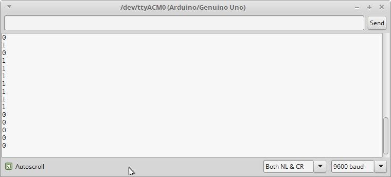
In the loop function, the value of the receiver is read. The retrieved value can either be LOW or HIGH. LOW means that the laser does not reach the detector, e.g., something went through the light barrier and is located between the laser and the detector. Then, the value of the detector is written to the console. Finally, a delay of 1000ms is added for convenience purposes (serial monitor is not “flashing” the values).
// (c) Michael Schoeffler 2014, http://www.mschoeffler.de

const int pinLaser = 2; // output signal pin of laser module/laser pointer
const int pinReceiver = 3; // input signal pin of receiver/detector (the used module does only return a digital state)

void setup() {
  pinMode(pinLaser, OUTPUT); // set the laser pin to output mode
  pinMode(pinReceiver, INPUT); // set the laser pin to output mode
  digitalWrite(pinLaser, HIGH); // emit red laser
  Serial.begin(9600); // Setup serial connection for print out to console
}

void loop() {
  int value = digitalRead(pinReceiver); // receiver/detector send either LOW or HIGH (no analog values!)
  Serial.println(value); // send value to console
  delay(1000); // wait for 1000ms
}
If the code has been successfully uploaded to the Arduino, the output on the Serial Monitor (Tools->Serial Monitor, Ctrl+Shift+M) should look like this:
Remarks:
The detector’s LED, which is located next to the detector, indicates whether the detector is connected to a power supply.
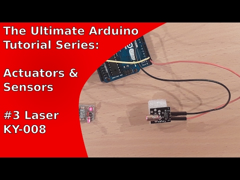
Video Tutorial:
I had major trouble with this until I realised that the laser ‘receiver’ was picking up the daylight for a reading rather than the laser!!
Hi, would you mind sharing the frizzing file of your project. I am looking for the light barrier to use in my own sketch. But I cant find it in the frizzing library provided.
Thank you so much, L.